How Work4Tec converted dense, imperfect laser-scan data into a As Build CAD Drawings deliverable for a leading U.K. survey firm — in just 12 working days.
From Point Cloud to Precision Model
View 01 — Floor Plan
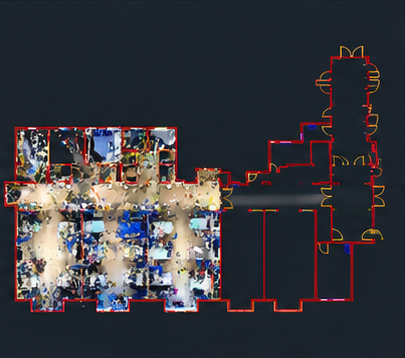 POINT CLOUD DATA
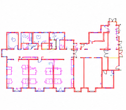 Finished CAD Floor Plan
View 02 — Elevation
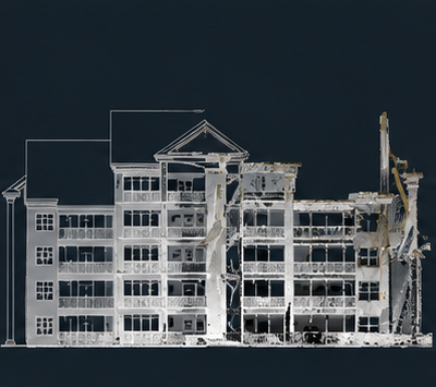 POINT CLOUD DATA
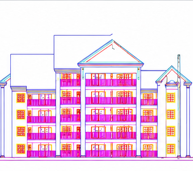 Finished CAD Elevation
A Compressed Timeline. An Uncompromising Spec.
Client Overview
A leading survey firm based in the United Kingdom, recognized for high-accuracy laser scanning and geospatial data capture across residential and commercial portfolios. For this high-density engagement, they needed a Drafting partner capable of turning raw, laser survey point cloud data into a construction-ready CAD drawing deliverable — fast enough to protect their own downstream commitments.
Project Overview
The client required a coordinated set of detailed 2D CAD drawings for a five-level residential building, developed from dense laser-scan point-cloud data. Work4Tec’s role was to interpret the available scan data and translate visible building geometry and services into a clear, organized drawing package suitable for design review, refurbishment planning and further project development. The deliverables were arranged on A0 sheets with consistent layers, annotations and drawing-set organization.
Four Pressures. One Deadline.

Dense and complex scan data
High-density point-cloud regions and variable scan visibility required careful interpretation to distinguish actual building features from noise and occlusions.

High-detail expectations
The drawing set needed to represent visible architectural details and MEPF elements without inventing information that was not supported by the scan.

Five-level geometry
Balconies, openings, roof transitions and repeated façade elements needed consistent representation across plans, elevations and sections.

Uneven coverage and occlusions
Some surfaces and service elements were partially obscured; the team needed to document only what could be reasonably verified from the available data.
A Workflow Built for Speed — Without Shortcuts

Reviewed the supplied point cloud and reference information, confirmed the required views, sheet expectations and level of detail.
Inspected scan coverage, aligned visible geometry across views and identified areas where occlusion or scan noise limited certainty.

Produced 2D CAD plans, ceiling plans, roof plan, elevations and sections with a structured layer and lineweight approach.

Included identifiable MEPF equipment and service elements where visible in the point cloud, avoiding unsupported assumptions.

Cross-checked repeated openings, floor-to-floor relationships, façade elements and geometry between related drawings.

Organised views into A0 sheets, reviewed readability and completeness, and prepared the drawing set for client review.
Results and Value Delivered
Completed the defined Scan to CAD drawing package within the 12-working-day target.
Converted dense point-cloud information into organised 2D CAD documentation for client review and downstream use.
Provided coordinated plans, ceiling plans, roof plan, elevations and sections in a consistent drawing structure.
Represented visible architectural and MEPF details to the extent supported by the scan data.
Delivered an A0-organised drawing set intended to improve review efficiency and reduce manual drawing coordination for the client.